

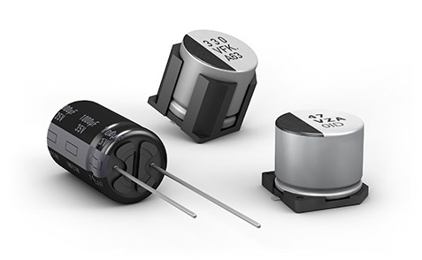
Control panels and power supplies in factories often fail without warning. A machine stops, production halts, and maintenance crews scramble to find the issue. Often, the culprit is a small, passive component inside the drive or power supply: the electrolytic capacitor. These components have a limited life by design. Learning how to extend electrolytic capacitor lifespan in industrial automation is a vital skill for anyone keeping systems running. By managing heat, ripple current, and electrical stress, you can push these components far beyond their standard ratings.
Understanding Electrolytic Capacitor Aging Mechanisms in Industrial Automation
To stop failures, you must understand how they happen. An electrolytic capacitor works by storing energy in an electric field between two aluminum foils. Between these foils sits paper soaked in liquid electrolyte. Over time, heat causes this electrolyte to dry out. As the liquid disappears, the capacitor loses its ability to store charge. It also loses its ability to smooth out voltage ripples.
Capacitor Lifespan Defined by Temperature
Temperature is the number one killer of these components. The relationship between heat and life follows a strict rule. For every $10^\circ \text{C}$ rise in operating temperature, the expected life of the capacitor is cut in half. If a capacitor is rated for $2,000$ hours at $105^\circ \text{C}$, running it at $115^\circ \text{C}$ drops that life to just $1,000$ hours.
As the electrolyte dries, the Equivalent Series Resistance (ESR) inside the capacitor starts to climb. Higher ESR means the capacitor generates more internal heat whenever current flows through it. This creates a cycle. Heat causes aging, aging raises resistance, and higher resistance creates more heat. Eventually, the capacitor fails completely.
The Impact of Ripple Current and Voltage Stress
Ripple current is the AC component that rides on top of your DC power. This current flows in and out of the capacitor, causing it to charge and discharge rapidly. This constant movement creates internal friction in the form of heat. While all capacitors generate some heat, excessive ripple current accelerates the drying process.
Modern variable frequency drives (VFDs) make this harder. They switch power transistors on and off thousands of times per second. This generates high-frequency noise and harmonics. These high-frequency currents are much harder on capacitors than the simple 60Hz ripple found in older gear. If your capacitors are not rated for these frequencies, they will overheat even if the average current seems low.
Mechanical and Environmental Degradation Factors
Factory floors are harsh environments. Constant vibration from motors and pumps can physically damage the seal of a capacitor. If the seal leaks, the electrolyte escapes even faster. Humidity and chemical vapors in the air can also corrode the leads and the metal can of the component. Always check that your cabinets are sealed against these external threats. Using high-quality capacitors with robust seals helps, but keeping the air around them clean is better.
Optimizing Thermal Management to Extend Electrolytic Capacitor Lifespan in Industrial Automation
You cannot stop a capacitor from generating heat, but you can remove it. Proper cooling is the most effective way to keep these parts running for years.
Implementing Precise HVAC and Cooling Solutions
Do not rely on passive ventilation if your cabinets run hot. Use active cooling systems that pull cool air directly into the cabinet and exhaust hot air out. The goal is to lower the ambient temperature around the component. Even a $5^\circ \text{C}$ reduction in cabinet temperature can significantly extend the life of your capacitors.
Clean your air filters often. A clogged filter traps heat inside, which cooks the electronics. Inspect your fans for signs of wear, such as noise or slow rotation. A fan that spins at 70% speed is moving much less than 70% of the air required. Replace them before they fail.
Strategic Component Placement and Layout
When designing or repairing a system, layout matters. Never place a capacitor bank next to a power resistor, transformer, or inductor. These parts get very hot. Use thermal barriers or extra space to separate sensitive components from heat sources.
Ensure that your PCB design allows for natural airflow. If you pack components too tightly, air cannot move between them. Keep vents on the enclosure clear of obstructions. Even small things like wire bundles blocking a vent can create a hot spot. Use thermal imaging cameras during normal operation to spot these hidden heat traps before they become problems.
Electrical Derating and Selection for Industrial Loads
Most engineers pick components based on the maximum voltage of the circuit. This is a mistake. To maximize life, you need to use a buffer.
Implementing Appropriate Voltage Derating Protocols
Operating a capacitor at its maximum voltage rating puts stress on the dielectric layer. For mission-critical systems, always derate your capacitors. Aim to run them at no more than $80%$ of their rated DC voltage. If your DC bus sits at 400V, use a capacitor rated for at least 500V. This extra headroom reduces the electric field stress, which slows down the chemical aging process inside the electrolyte.
When calculating voltage, account for transients. Motors generate back EMF (electromotive force) when they decelerate. This can spike your DC bus voltage. Your capacitor must be able to handle these spikes without exceeding its rating.
Selecting Low-ESR and High-Temperature Capacitors
Not all capacitors are built the same. Standard parts are fine for low-power consumer electronics, but they will fail quickly in a motor drive. Look for parts with a “low ESR” rating. These parts handle ripple current with less internal heating.
Check the temperature rating on the datasheet. Always choose components rated for $105^\circ \text{C}$ or higher, even if your cabinet runs cooler. These parts use higher-quality electrolytes that last longer at lower temperatures. If you work with high-frequency switching, look for capacitors specifically rated for high-frequency impedance.
Mitigating Ripple Current Stress Through Filtering Design
If you cannot change the load, change how the load sees the capacitors. Filtering helps smooth out the current and protects your bulk storage.
Effective Input Filtering and Line Conditioning
Upstream filters are your first line of defense. EMI and RFI filters block high-frequency noise from reaching your power supply. By cleaning up the power before it hits the DC link, you reduce the stress on the capacitors. Use input inductors (also called line reactors) to smooth out current draw. These inductors act like a shock absorber for the power supply, preventing sudden current spikes from hitting the capacitors directly.
Utilizing Capacitor Banks for Load Balancing
Do not use one giant capacitor if you can avoid it. Use a bank of several smaller, parallel capacitors. This spreads the ripple current across multiple components. If each capacitor carries only a fraction of the total current, each one runs cooler. This arrangement also helps with voltage distribution. If one capacitor fails short, others in the bank can sometimes keep the system running until the next maintenance cycle. Ensure that you use matching capacitors in these banks to balance the load evenly.
Implementing Predictive Maintenance and Monitoring Strategies
You should never wait for a capacitor to explode or leak. Use data to find failing parts before they cause downtime.
Condition Monitoring: ESR and Capacitance Measurement
Build a schedule to test your critical capacitor banks. You do not need to pull them off the board to test them. Use a high-quality ESR meter or an impedance analyzer designed for in-circuit testing.
Watch for two things:
- Capacitance drop: A significant drop in capacitance means the electrolyte has dried out.
- ESR increase: A rise in ESR indicates the part is degrading.
Keep a log of these readings over time. If you see a trend of rising ESR, schedule a replacement during a planned shutdown.
Integration of Online Health Monitoring for Critical Systems
Modern automation allows for real-time monitoring. Many high-end drives now track their own internal temperatures and DC bus ripple. Integrate these values into your SCADA or PLC dashboard. Set alarms for high ripple current or unusual temperature spikes. If the drive reports that the DC bus ripple is higher than the baseline, you have an early warning that a capacitor bank is nearing the end of its life.
Conclusion
Extending the life of electrolytic capacitors is not about luck. It is about controlling the environment and reducing the stress on the components. Heat and ripple current are the two main factors that drive failure. By keeping the air cool, using voltage derating, and selecting parts with low ESR, you remove the biggest threats to your system. When you combine these design choices with regular testing and online monitoring, you build a system that runs longer and fails less often. This proactive work protects your production uptime and reduces the total cost of ownership for your automation equipment.
